There are quite a few different kinds of motors: DC motors and stepper motors to name two. DC motors are normally used for mobile robots as they are relatively easy to use, they go relatively fast and their speed can be controlled. The downside is that they normally require encoders to obtain feedback to drive straight. Stepper motors on the other hand are relatively slower, more accurate in motion, and are open loop systems (no feedback).
So how does a stepper motor work? A good explanation video I’ve found is linked here: http://youtu.be/bngx2dKl5jU. Basically there are bipolar and unipolar stepper motors. This pertains to the number of pairs of coils inside the motor. The motor is driven by magnetism at its core. In unipolar motors, there are two pairs of identical coils, one pair per phase. A controller passes current to one pair of coils and this changes the magnetic polarity of the coils. Since the coils are alternated, by alternating the magnetic polarity of the phases you have a switching effect of going North to South polarity over and over. This causes driven motion when the center gear is magnetized, causing the gear to be attracted to the coils of opposite magnetic polarity. The gives a sort of production line effect as the gear begins to rotate as it follows the alternating polarity of the coils. Now this is just my understanding of how the motor works, if you wanted to know more I’d suggest googling how stepper motors work.
Now what about MY Nema 17 Stepper Motor? Well the product page is here: https://www.oyostepper.com/category-2-b0-Nema-8-Stepper-Motor.html . Well NEMA stands for National Electrical Manufacturers Association. It basically is a standard motor mounting geometry and the 17 means the dimensions of the motor is 1.7” x 1.7”. This motor has a 1.8° step angle, which means 200 steps/revolution of the motor. The reason I chose to use a stepper motor, was that Beethoven Bot does not roam or follow, he moves from note to note, meaning he doesn’t need to travel fast, rather he needs to be accurate. Thus a stepper motor would be more ideal than the DC motor since the stepper motor moves in steps/revolution.
Now the stepper motor comes with four cables, two for each phase, which means we need to have something to control which cable passes current at what time. This task is completed by motor driver carriers. The motor driver carrier I ended up with is http://www.infomapp.com/p/can-i-simply-use-larger-stepper-motor/. This is a low voltage stepper motor driver carrier, which operates between 2.5–10.8 V and can deliver up to approximately 1.5 A per phase. Essentially, the motor driver takes two power supplies, a logic level 3.3V or 5V and a driving power supply 2.5-10.8 V to run the motors. A 100uF capacitor is recommended between the driving power supply and ground. And STEP and DIR pins are input from a microcontroller to tell the motor driver how many steps to go and in what direction.
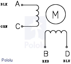
The wiring of the motor is in pairs along with the motor driver wiring are shown below :